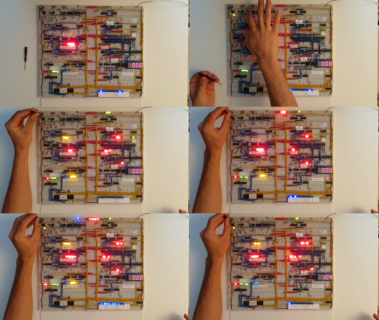
on
Building an 8 bit computer on a breadboard
Following the terrific online course FromNand2Tetris that I previously wrote an article about, I decided to commit to Ben Eater’s Youtube Series, in which he builds a fully functioning 8-bit computer from mere logic gates and 74LS series chips, on a breadboard. I first stumbled across this project with a couple of fellow students during my studies in China, but without the time or dedication required for such a project, we unfortunately never made it past the clock module.
Anyways! Ever since, I had this project stuck in the back of my head, and being naturally stubborn, I decided to tackle it some time in January this year.
I have quite the journey behind me.

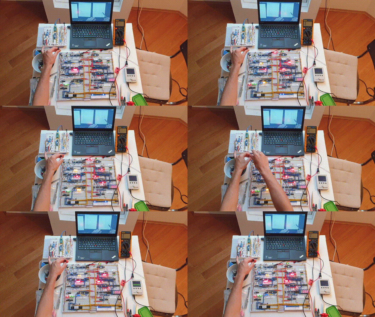
My workspace.
Without a doubt, this constitutes the single-most demanding project I have undertaken. Not necessarily in terms of time, but certainly in terms of perseverance and determination! At the same time as teaching me about electronics and computer architecture, I consolidated my credo about intrinsic motivation — I might write a post about this personal discovery at some later stage.
Computer modules
Alright, let’s get to the computer. In essence, it consists of the following modules:
- The clock module: This module creates short impulses that feed into the many electronic components that have to be kept in sync and is built using several 555-Timers and some basic logic gates.
- The “A” and “B” registers: These two 8-bit registers both feed into the ALU and can be addressed separately. Each register is built using two
74LS173sand a74LS245for BUS communication. - The Arithmetic Logic Unit (ALU): In essence built out of two 4-bit adders (
74LS283), two XOR-Gates (74LS86) and a74LS245for BUS communication. - The Flags Register: The Flags Register stores 2 values. The Carry Flag, which goes high when an arithmetic operation overflows, and the Zero Flag, which goes high whenever a calculation yields
0. This register is also built using a74LS173Integrated Circuit (IC). - The whopping 16 bytes of Random Access Memory (RAM): The data itself is stored in two
74LS189RAM chips (with a small inverter fix using74LS004s). Using some multiplexers (74LS157), one can switch between Programming mode and Running mode. In programming mode, the user can write some program to RAM using some DIP switches. - The Program Counter: A simple counter (
74LS161) that connects to the BUS and is used to address RAM to query a program. It can be set using (conditional)jump-instructions, which is what makes the computer Turing-complete. - The Display Unit: The display unit, as the name suggests, displays numbers up to 255 on a 7 segment display. An electrically erasable programmable read only memory chip (
28C16EEPROM) is used to control the respective display segments of 4 individual displays. Displaying negative numbers as their Twos-complement is also possible. - The Control Unit: The Control Unit decodes every instruction after it has been fetched from memory. It is built using two
28C16EEPROMs and runs through 5 microcode steps per instruction.
Reflection
I cannot begin to describe how much I learned from building this computer. Previously, I knew little to nothing about electronics. Everything I knew about computer architecture built upon the great Online Course FromNand2Tetris. I didn’t understand much about the inner workings of logic gates, registers, the clock module, microcode decoding, tri-state logic and so many other topics that interface with digital logic and computer architecture. Ben Eater pretty much taught me all of that and I’m incredibly excited that these resources are freely available on the Internet. You should really browse his website to get an idea of how powerful his content is.
